Power
feed for Sherline lathe
This
article assumes you have read Sherline Lathe
Infrastructure.
I
wanted to add a power feed to my 17-inch Sherline
lathe to make machining easier and smoother.
This involved adding a stepper motor and some electronics to the
lathe. The stepper motor is used to turn
the lead screw as if the lead screw was being turned by the X axis handwheel.
Following
are instructions if you want to do the same.
At the end of the article is a parts list. I have included URLs for parts if you want to
get them from Amazon. The parts are also available from other sources if you
prefer. Note that this system would be a
tight fit on an 8-inch lathe. This setup
assumes that the lathe is mounted on a base as described in Hacks on a Sherline Lathe.
I
used a NEMA 23 stepper motor and mounting bracket, a TB6600 MIcrostep
Driver, a simple pulse generator, a small relay module and a DPDT (on)-off-(on)
switch. The stepper motor and TB6600
driver used 24 vdc so I used a 24 vdc power supply. The pulse generator, the relay and the TB6600
control signals required 5vdc so I also used a 24vdc to 5vdc converter.
The
relay module is needed because the TB6600 enable input (ENA) defaults to
enabled if there is nothing connected to it.
I connected the TB6600 ENA+ to the normally closed terminal on the relay
and +5vdc to the common terminal so that the default would be that the TB6600
is disabled. The switch drives the relay
such that the relay is engaged and the TB6600 is enabled when the DPDT switch
is switched to one side or the other.
This means that the stepper motor does not run when the switch is in the
center (off) position but does run when the switch is moved to the left or to
the right. The other terminals on the switch are used to
send +5vdc to the DIR+ terminal or to leave that terminal disconnected. This determines the direction the motor will
run. (See figure 3.)
I
used some parts from the Sherline thread cutting
attachment to get access to the lathe’s drive shaft.
The first thing to do is to install the
fixed shaft, sliding shaft and engagement lever from the Sherline
thread cutting attachment following the instructions for installing
the attachment.
This
installation involves taking the lathe apart – note do not take out the flat
head screw in the middle of the lathe bed at the tail end and only loosen the
one at the head end to put in the sliding and fixed shafts and pay attention to
the instructions about lining up the gap in the fixed shaft with the screw. Use the hex head screws in the blind holes at
each end of the bottom of the lathe base to release and reattach the lathe bed. I drilled holes in the plywood base to allow
access to the holes for the screws holding the lathe bed to the base.
I
used 60 tooth, 5mm bore, timing pulleys designed for a
6mm timing belt for both the stepper motor and the fixed shaft extension of the
lead screw to provide a 1:1 ratio between stepper motor speed and lead screw
speed. I also used a 320 tooth 6mm timing belt to connect the stepper motor to
the drive shaft. You need to drill out the bore of one pulley to 8mm to match
the shaft on the stepper motor. Using a 3/8 end mill in the lathe or in a mill,
you need to cut a 3/8 dimeter shelf about 3/32 deep in the other pulley and,
using a 1/8” end mill, cut a lobe on one side of the 3/8 shelf. This is to fit
the end of the thread cutting attachment fixed shaft. (See figure 1.)
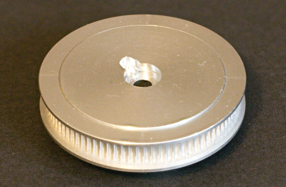
Figure 1: lead
screw pulley
Mount
the modified pulley on the end of the fixed shaft using a hex driver 10-32
bolt. You may need a flat washer on the
bolt to keep the bolt head from going into the hole in the pulley.
You
then need to figure out where to mount the stepper motor so that belt is just
tight enough. To do this, mount the stepper motor on the bracket. Mount the other
timing pully on the stepper motor. Put the timing belt on the pulleys and
position the steeper motor and bracket so the belt is straight &
tight. Trace an outline of the bracket
base on the plywood. Remove the pulley
from the motor and the motor from the bracket and, using the outline you just
made, position the bracket & screw it down to the plywood with #6 1/2"
round or pan head wood screws. Reinstall the stepper motor, pulley & timing
belt. (See figure 2.)
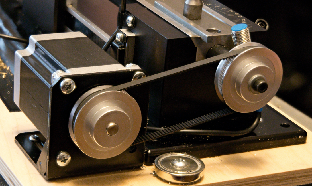
Figure 2: stepper
motor installed with belt and pulleys
I
cut a hole in the plywood just behind the stepper motor and ran the stepper
motor cable through the hole and under the plywood to the electronics box that
I placed at the back right of the plywood base so that the cable would not
become a chip trap.
Assemble
the electronics (see figure 3) and connect the stepper motor to the
driver. Set switches 4-6 on the TB6600
to select 3 amp (off-on-off) current. Set switches 1-3 to the number of pulses you
want to have per revolution of the stepper motor shaft. I found that the number of steps did not make
a great difference in the actual top speed of the stepper motor – that seemed
to be determined by the stepper motor itself. I wound up using 800 pulses per
revolution (on-off-off).
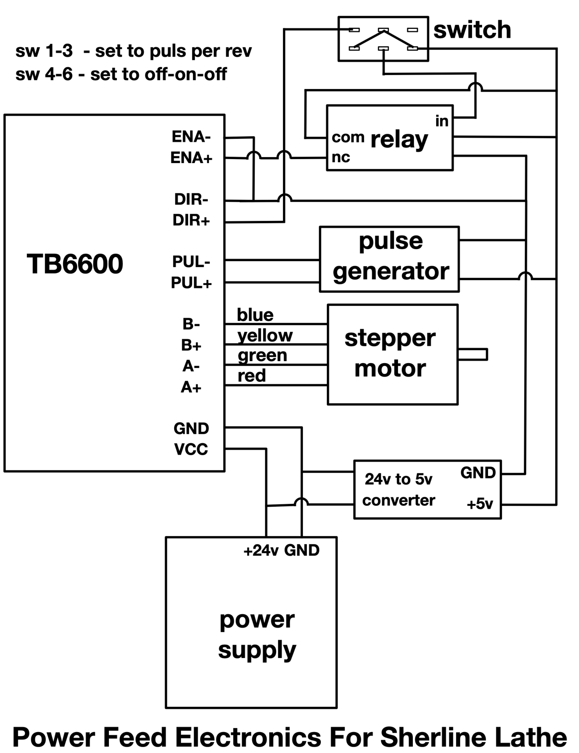
Figure 3: diagram
of electronics for power feed
I
put the switch on the aluminum bracket that I mounted under the lathe bed
alongside of the pulse generator. (See
figure 6.)
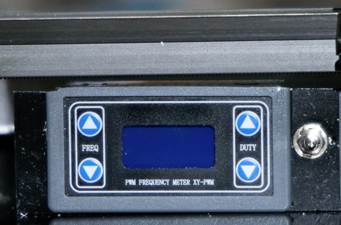
Figure 6:
installed pulse generator and control switch
I
mounted the switch so that the action is horizontal. Pushing the switch to right causes the saddle
and crosslide to move to the right, and pushing the
switch to the left causes the saddle and crosslide to
move to the left. The pulse generator can be adjusted to set the speed that the
saddle moves. I used a momentary switch so that the moving saddle is less
likely to move out of control and cause damage.
To
use the power feed, you rotate the engagement lever (see figure 8) clockwise while
manually turning the lead screw with the tailstock drive wheel until the flat
spot in the sliding shaft engages with the flat spot in drive shaft. Then you can
push the switch right or left to power feed the saddle and crosslide.
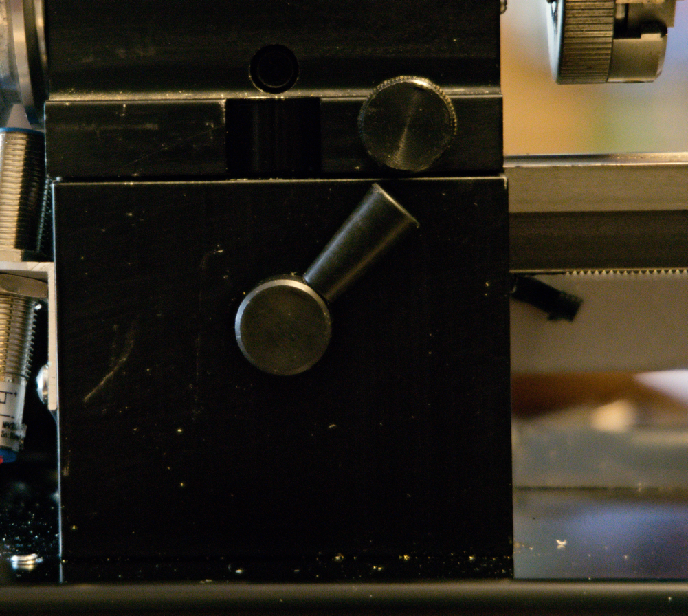
Figure 8:
engagement lever
Parts
list for power feed
The non-Sherline
links here point to Amazon but the same parts are available from many other
sources if you prefer to not deal with Amazon.
Sherline Fixed shaft - part
#15430
Sherline Sliding shaft - part
#15090
Sherline Engagement lever -
part #15420
Mounting bracket
for the stepper motor
timing pulleys (2)
– 60 tooth 5mm bore for 6 mm belt
Copyright
Ó 2024 Scott
Bradner
2024-09-05