2
Axes DRO for Sherline lathe
This
article assumes you have read Sherline Lathe
Infrastructure.
This
article describes how to install an inexpensive X-Y digital read out (DRO) on a
Sherline lathe with the machined base.
Sherline
does sell a DRO kit for its lathes (part no 8200) but their DRO is
quite expensive and does not actually tell you where the tool bit is and the
display is annoying because it only displays the X position or the Y position
not both at the same time. The kit does
include a tachometer but you can put a tachometer on the lathe for less than
$30. (See separate article.)
I
say that the Sherline DRO does not actually tell you where the tool is because
it depends on the rotations of the handwheels and does not account for backlash. This article describes a DRO which shows the
actual movements of the crossslide and of the saddle and thus shows the actual relative
location of the tool. In addition, it is
quite a bit cheaper than the Sherline unit.
There
are two different parts: the crosslide DRO (Y axes) and the saddle DRO. (X
axes)
The
Y axis DRO.
The
Y axis DRO is basically a 6-inch digital caliper with pieces cut off and
mounted on the crosslide. There are many
sources for this size caliper online. You
want to get one with a plastic body with the rest in stainless steel because
you will need to sand off parts of the body to get a good fit. Figure 3 shows the basic type of caliper you
should get. You can get the level of precision
that you want from 2 decimal places to 4 and, for more money, 5. Figure 1 shows
the modified caliper installed on the lathe.
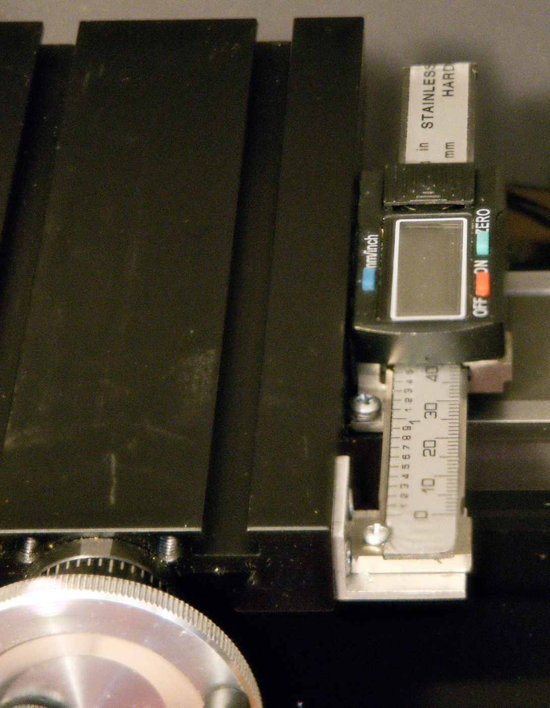
Figure 1:
Crosslide DRO
Figure
2 shows the cuts needed on a 6-inch digital caliper. The cuts can be made with a cutoff saw, or,
in the case of the plastic core, a sander.
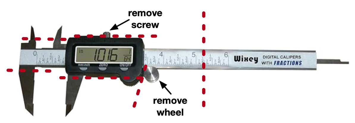
Figure 2: cuts
needed to a digital caliper
Figure
3 shows the result of the cuts and shows the two holes that need to be drilled.
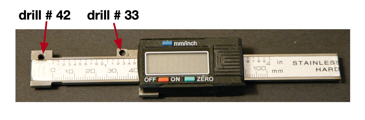
Figure 3: digital
caliper after cuts
You
need to drill and tap the crossslide and saddle in three places 4-40 screws –
see figure 4.
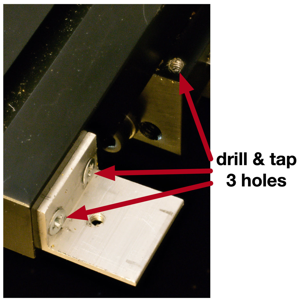
Figure 4: drill
and tap locations
Figure
4 also shows the small aluminum bracket that is needed to support the end of
the caliper. The hole in the bracket is
a #42. The caliper is bolted down to the
saddle with a 3/26 long 4-40 screw with a lock washer and bolted to the bracket
with a 3/16 2-56 screw, lock washer and nut.
The top of the caliper should just clear the side of the crosslide. The result should be what is shown in figure
1.
The
body of the caliper is fixed to the saddle and the slide of the caliper is tied
to and moves with the crosslide and thus shows the position changes of the
crosslide.
X
axes DRO
The
X axes DRO is not much more complex. It
is based on an iGaging Easy-View 24-inch DRO cut down to 20 ¾ inches with a
hack saw. There are many sources for
this online, with prices ranging from $42 to $179. See figure 5.
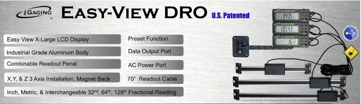
Figure 5:
Easy-View DRO label
The
shortened iGaging bar is bolted to the back of the lathe base. See figure 6.
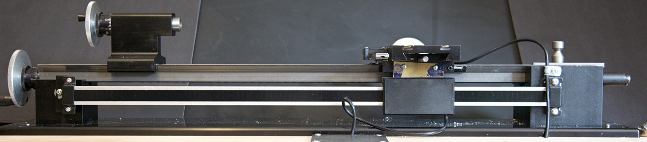
Figure 6: lathe
back view with DRO sensor & bar
The
tailstock end of the measurement bar is bolted to the lathe base with a single
8-32 screw with some washers acting as a spacer to line up the bar with the
edge of the lathe bed. One 8-32 hole
needs to be drilled & tapped into the tailstock pillar on the lathe base.
See figure 7.
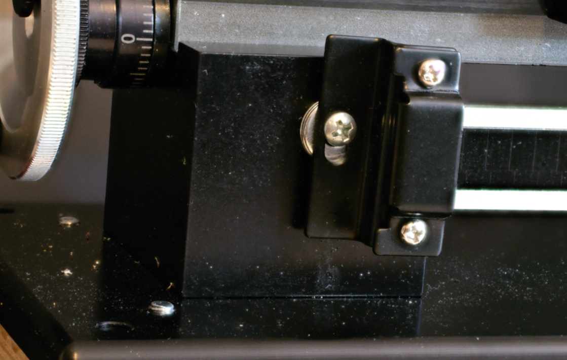
Figure 7: DRO bar
mount tail end
At
the headend the bar is fastened to the pillar with half of the bracket that
comes in the kit along with a small block of ¼ inch thick aluminum as a
spacer. Two 4-40 holes need to be
drilled and tapped to mount the bracket at this end. A third 4-40 drilled and tapped hole is used
for a cable clamp to hold the cable going from the slide sensor to the display.
See figure 8.
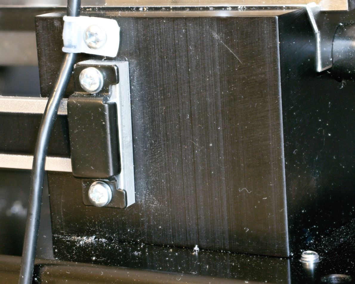
Figure 8: DRO bar
mount head end
The
slide sensor is connected to the saddle with a small sheet of thin brass that
is bolted to the two 4-40 holes drilled and tapped into the saddle at the top
and to two pre-tapped holes in the back of the slide sensor. Figure 9 shows this from the back.
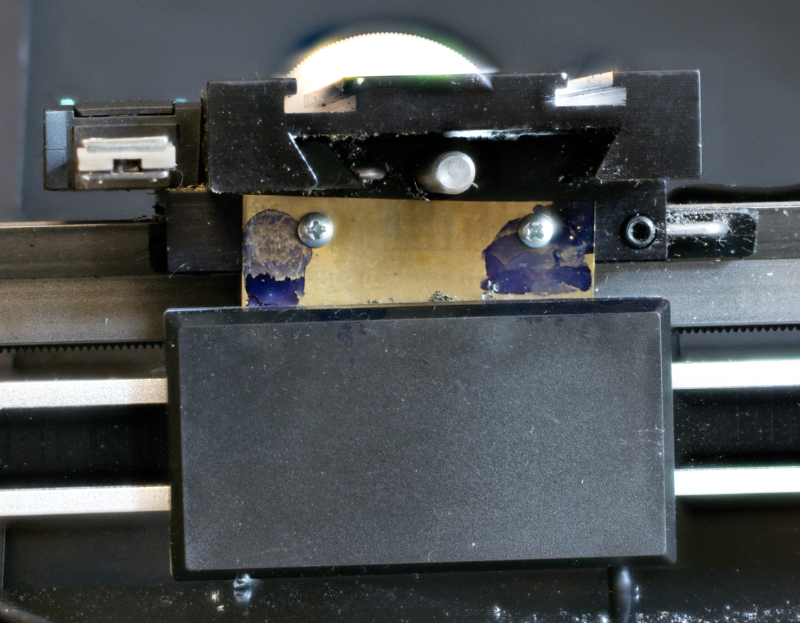
Figure 9:
connection between DRO sensor and saddle
Figure
10 shows the sheet of brass mounted on the back of the slide sensor.
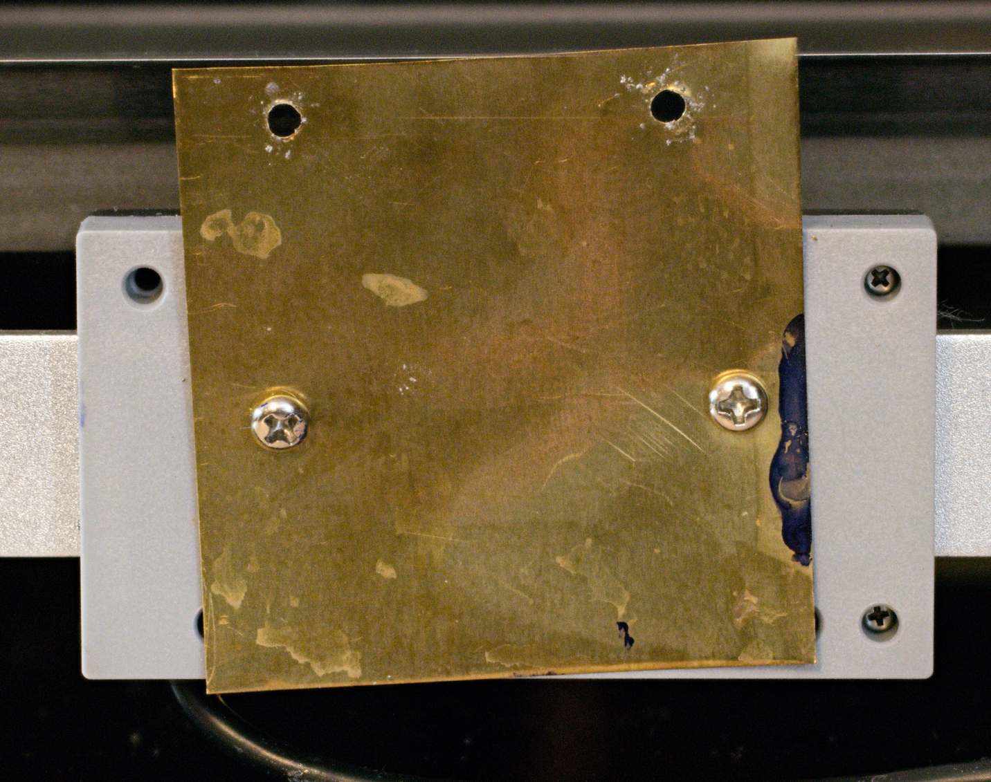
Figure 10: back of
DRO sensor showing brass sheet
I
coiled the sensor cable under the lathe’s plywood base and secured it with
cable clamps. I drilled the hole for the
cable at the center point of the measurement bar and drilled the exit hole in
back of the head end of the lathe base. See figure 11. If you are also installing a lead screw power
feed or converting the lathe to use a stepper motor drive (see separate
articles) the end of the DRP cable can go through the hole that you make for
the stepper motor cables. (See figure 7 in the Hacks on a
Sherline Lathe
article.)
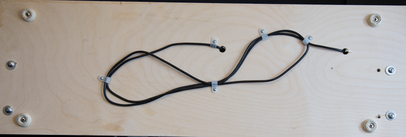
Figure 11: under
lathe plywood base
I
mounted the DRO display on a bracket I made connected to the control housing
for the lathe motor. See figure 12.
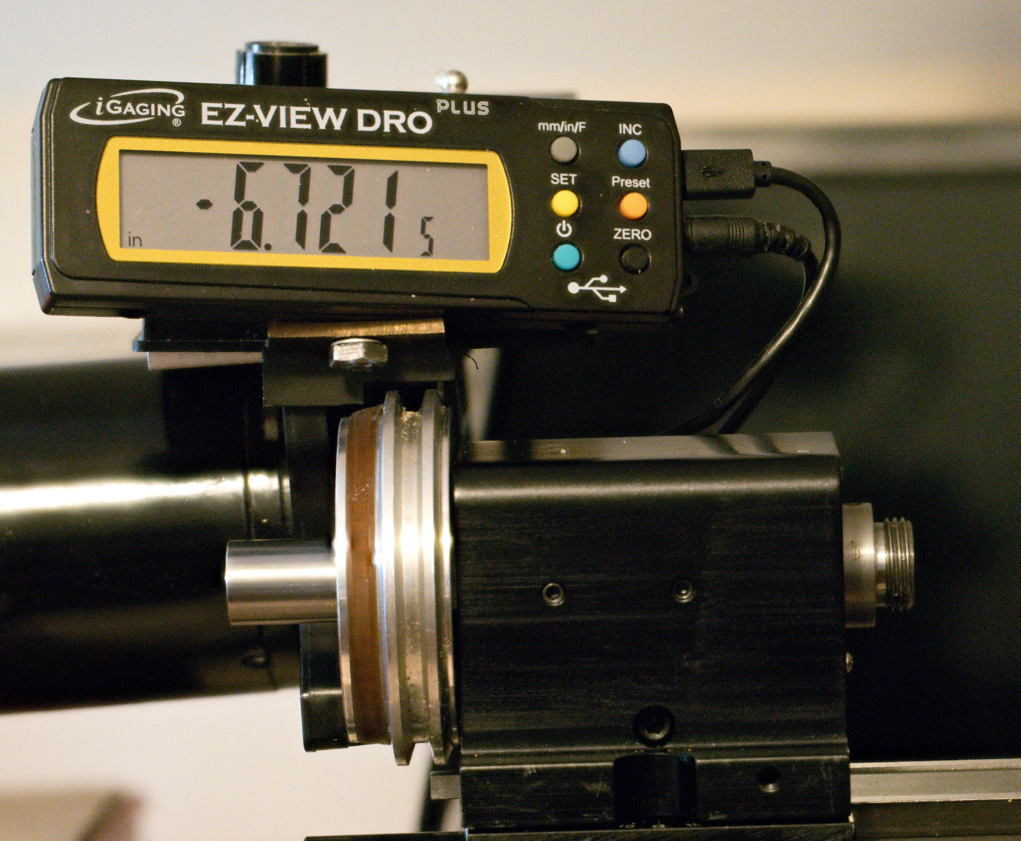
Figure 12: DRO
display on lathe with Sherline motor and control
Figure
13 shows the bracket.
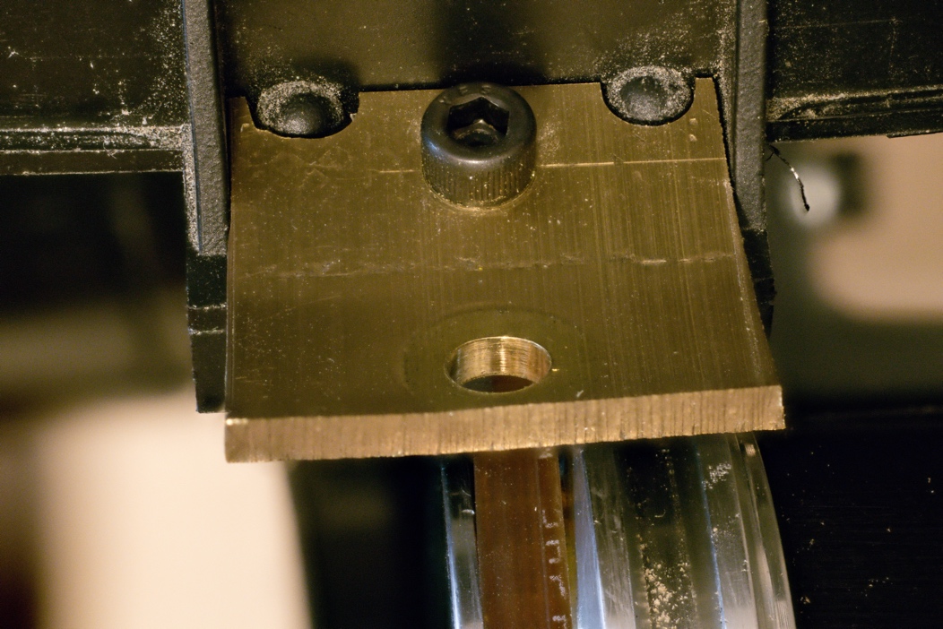
Figure 13: DRO
display bracket for lathe with Sherline motor and control
I
also made a bracket to mount the display on the stepper motor holder for my
lathe after I converted the lathe to use a stepper motor. (See separate article.) See figure 14.
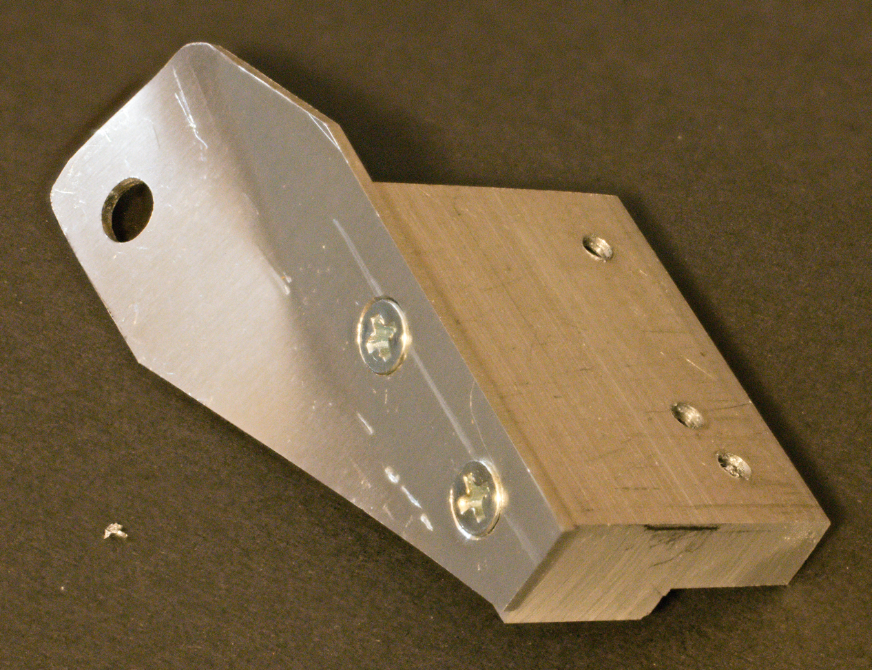
Figure 14: bracket
for DRO display on Sherline lathe with stepper motor drive
Figure
15 shows the DRO display mounted on the spindle drive stepper motor bracket.
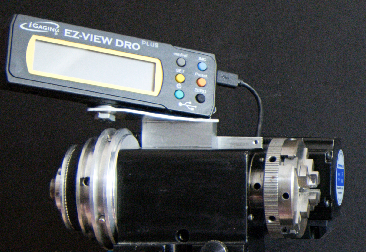
Figure 15: DRO
display on Sherline lathe with stepper motor drive
Parts
list
iGaging Easy-View 24-inch DRO
6 inch digital caliper
Copyright
Ó 2024 Scott
Bradner
2024-09-05