Tailstock
DRO for a Sherline Lathe.
I
decided that a tailstock DRO would be useful on my Sherline
Lathe. It turned out to quite easy to do
and quite cheap.
I
based the tailstock DRO on a 6-inch digital caliper. I made some cuts on the
caliper with a cutoff saw. See figure 1.
The two holes in the prongs are #33, which is the body brill for 4-40
screws.
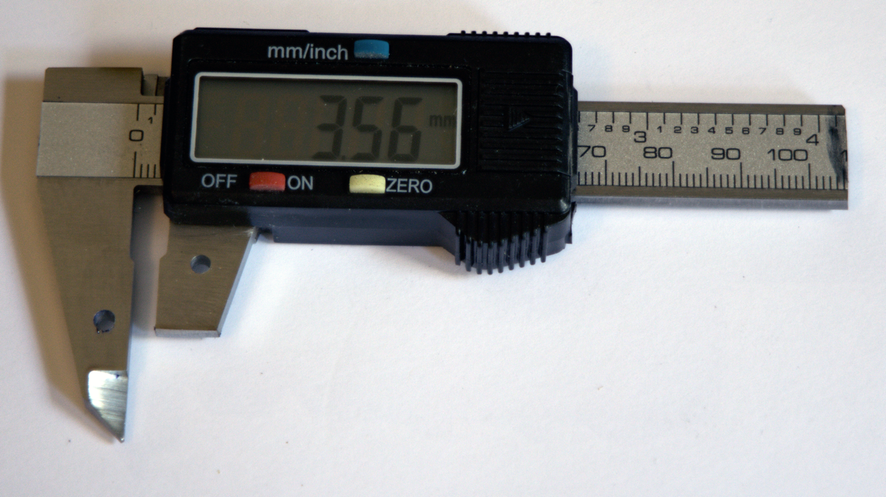
Figure 1: modified
6-inch digital caliper
I
then made a small bracket to mount the caliper on the tailstock. See figure 2.
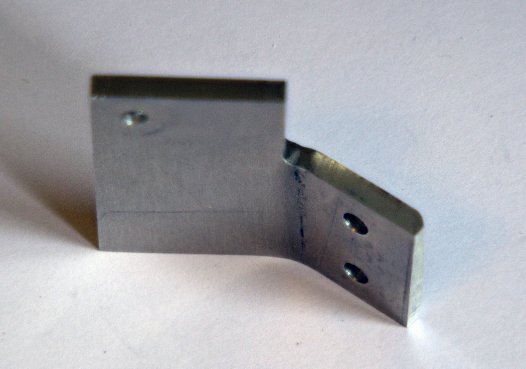
Figure 2: bracket
I
made the bracket out of 3/32 aluminum sheet but 1/16 would work just as well
since the bracket is not the subject to much stress. The part of the bracket on the right with two
holes will get bolted to the back of the Sherline
headstock. The holes are #28 which is
the body drill for 6-32 screws. The hole on the left part is #33, which is the
body drill for a 4-40 screw. A 4-40
screw will pass through this hole and through a #33 hole in the right prong on
the caliper shown in figure 1. The
angle of the bend is to let the caliper lay back so it is easier to see, you
should pick an angle that works for you.
I
then drilled and tapped two 6-32 holes in the back of the Sherline
tailstock. See figure 3.
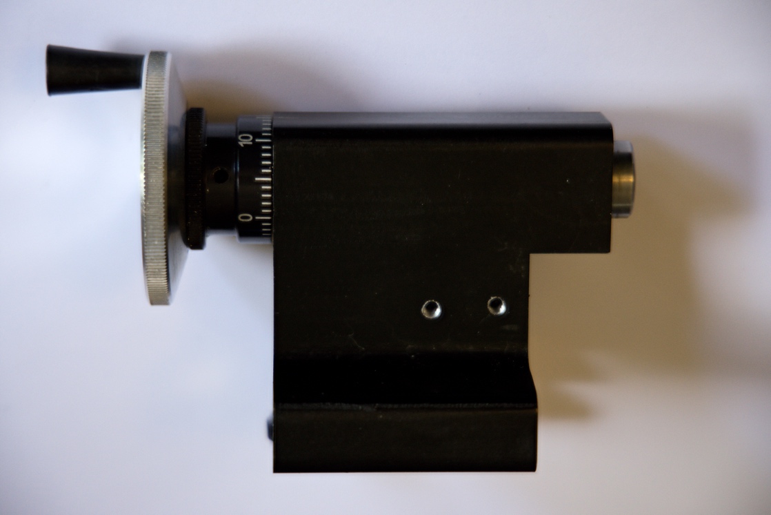
Figure
3: Sherline tailstock with tapped holes for bracket.
The
DRO works by fixing the body of the caliper to the tailstock and fixing the
slider of the caliper to the front of the tailstock’s spindle. The front ¼ of an inch of the spindle can be
used for a bracket since it does not not interfere with the function which
ejects things that have been put into the MT0 taper in the spindle.
I
first mounted the bracket to the tailstock with two 3/8” 6-32 round head screws
with lock washers. I then manually lined
up the fixed caliper prong with the bracket to figure out where to drill a hole
in the bracket and a matching one in the prong.
After drilling the holes, I bolted the caliper to the bracket with a
3/8” long 6-32 round head screw, lock washer and nut. I used a single screw to
hold the caliper to the bracket so that the system would have some flexibility
if the position of the caliper was a little bit off.
I
made a ¼” thick disk out of a piece of 1 ¼” diameter aluminum bar that I had
around. The disk has a hole in the
center that fits tightly over the tailstock spindle. I put the disk onto the tailstock spindle and
put some layout fluid on the disk so that lines would show up. I then scribed the side of the caliper’s
sliding prong so that I would know where to shape the disk so that the prong
would fit against it. See figure 4.
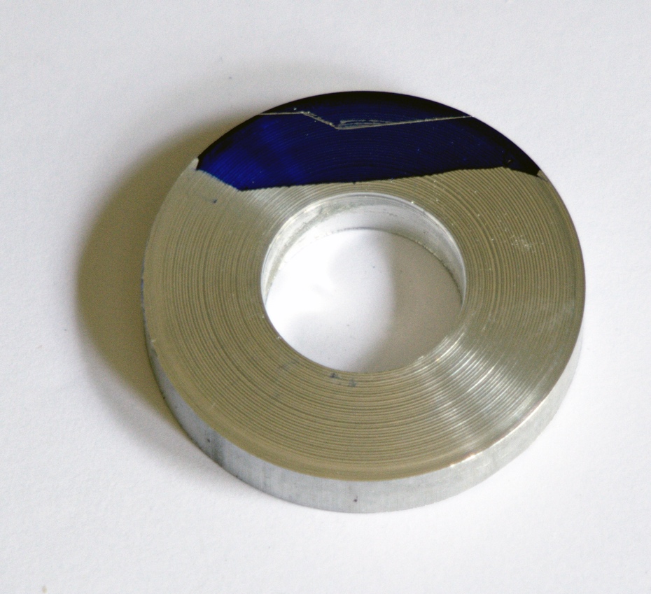
Figure 4: disk
marked showing the edge of the caliper prong
I
cut off the side of the disk with a band saw & a disk sander. I then mounted the disk on the tailstock and
lined up the caliper prong to figure out where best to put the hole for
fastening the prong to the disk. After
figuring that out and drilling a #33 hole in the prong I reinstalled the
caliper and used the hole to mark where the matching hole needed to be drilled in
the disk and then drilled and tapped the disk.
I
then drilled and tapped a 4-40 hole for a set screw to hold the disk to the
tailstock spindle. The hole for the set
screw is positioned so that the set screw goes into the slot in the tailstock
spindle. Then I shaped the disk with the
band saw and sander to make it look better.
I
put the disk back on the tailstock spindle and bolted the sliding prong onto
the disk using a 3/8” 4-40 screw and lock washer. Then I screwed a 4-40 set screw into its hole
to secure the disk to the spindle. Then
I put the tailstock back on the lathe.
Figure
5 shows whole thing put together and mounted on the lathe.
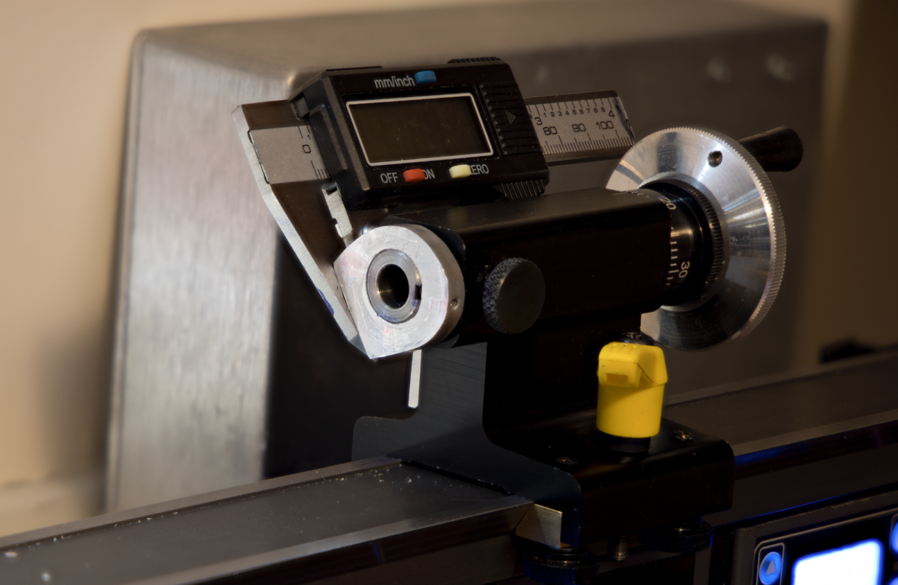
Figure 5:
Tailstock DRO mounted on the lathe showing the shaped disk
Figure
6 is another view of the DRO.
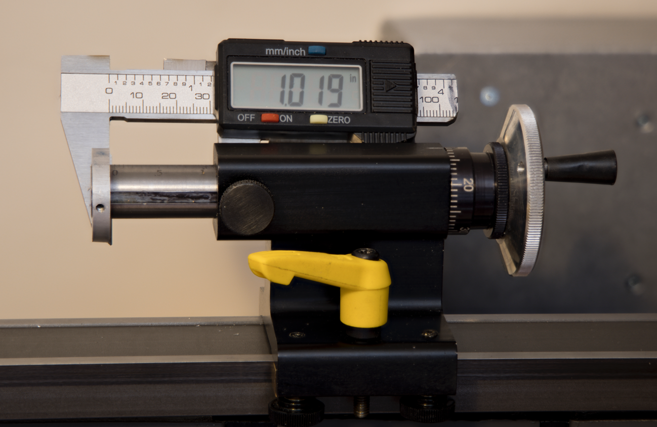
Figure 6: DRO
mounted on lathe
Copyright
Ó 2024 Scott
Bradner
2024-09-05