Stepper
motor drive for Sherline lathe
This
article assumes you have read Sherline Lathe
Infrastructure
I
upgraded my old 8-inch Sherline lathe to a 17-inch version. The new lathe,
obviously, was wider than the old one.
The increased width made worse by the fact that the lathe’s motor sticks
out to the left a long way. In my case,
I am using a roll around tool box as a base for the lathe, the lathe itself
fits the base just fine but the motor stuck out to the left 6 inches and got in
the way of a Sherline mill on another tool box to the left.
I
thought that there might be an option to use a stepper motor that would not
stick out as much. I looked at
Sherline’s stepper motor
mount options.
It looks quite kludgy and not all that strong.
It also only accommodates a rather small stepper motor and says the max
RPM is 225. I thought I could do better
than that. The system described in this
article uses a much bigger motor and can go over 2,000 RPM if you are careful.
I
decided to use a closed-loop stepper motor and control because I found that the
open loop systems tended to stall when being started at higher speeds and I
found far less of that issue with closed loop systems. I decided to use a NEMA 23 sized motor since
it closely matched the size of the Sherline headstock and I decided to use the
424 oz.in motor to ensure that I had plenty of power. (See parts list at the end of this article.)
I
first made an aluminum bracket to hold the stepper motor to the Sherline
headstock. See Figure 1.
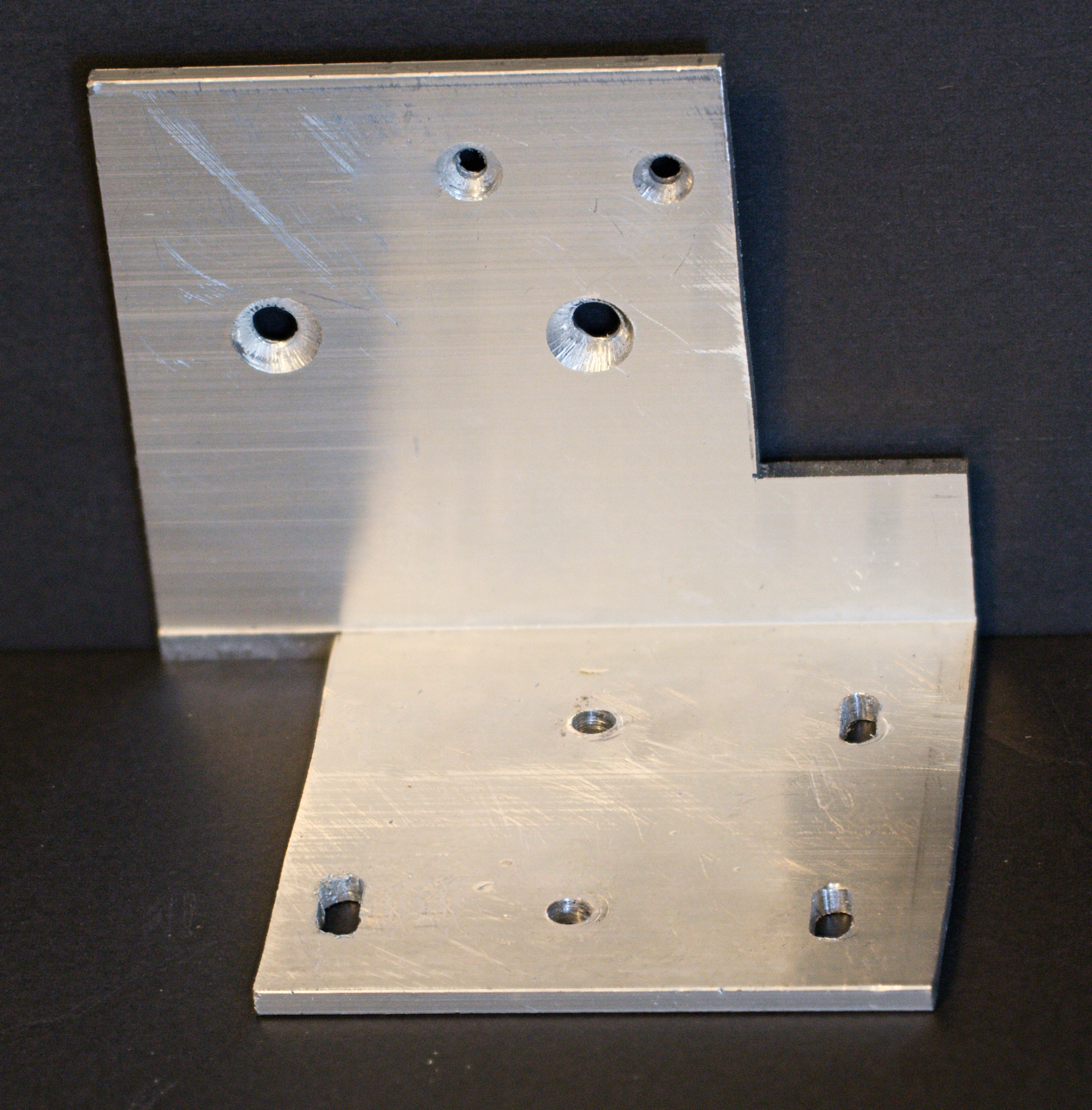
Figure 1: stepper
motor bracket
The Bracket is made from a 3 ¾ inch long
piece of 3 inch by 3 inch by 1/8 inch aluminum angle. You can also use the ¼ inch thick angle which
seems to be easier to get. The bracket
is bolted to the holes in the side of the Sherline headstock with 8-32 flat
head screws through the two countersink holes on the vertical part of the
bracket. The location of the holes is
such that the bottom of the angle lines up with the bottom of the headstock so
as to not interfere with the lathe base.
The two holes at the top of the vertical part of the bracket are to hold
a bracket for a DRO display. (See separate article.) If you are not going to install the DRO you
can cut the bracket off above the two mounting holes
The 3 slots in the horizontal part of the
bracket are to hold a piece of ¼ inch aluminum on which the stepper motor
bracket is mounted. They are slots to provide some amount of adjustment to
tighten the drive belt. There are three
because I could not figure out how to make a fourth because I could not get the
milling head in the right place to make it.
(I used a Sherline mill to make the slots.) The other two holes were
used to mount a block of aluminum that I used to hold the bracket when I was
milling the slots.
The length of the horizontal part of
the bracket was determined by the length of the bracket for the stepper motor.
The cutout on the right side of the vertical part of the bracket is to clear
the pulleys on the Sherline headstock.
I
used two 80 tooth, 8mm bore, timing pulleys and a 320 tooth 6mm wide timing
belt. You heed to bore out one of the timing pulleys to a bit more than 9/32 to
fit on the headstock spindle.
Figure
2 shows the bracket mounted on the headstock.
It also shows the ¼ inch aluminum piece that the motor bracket is bolted
to and can be slid back and forth using the slots milled into the bracket.
Finally, Figure 2 also shows the timing pulley mounted on the headstock
spindle.
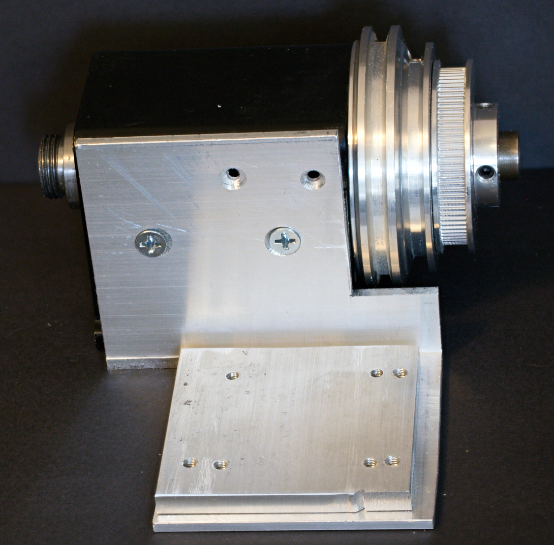
Figure 2: stepper
motor bracket bolted to headstock
Figure
3 shows Figure 2 with the addition of the steel stepper motor bracket.
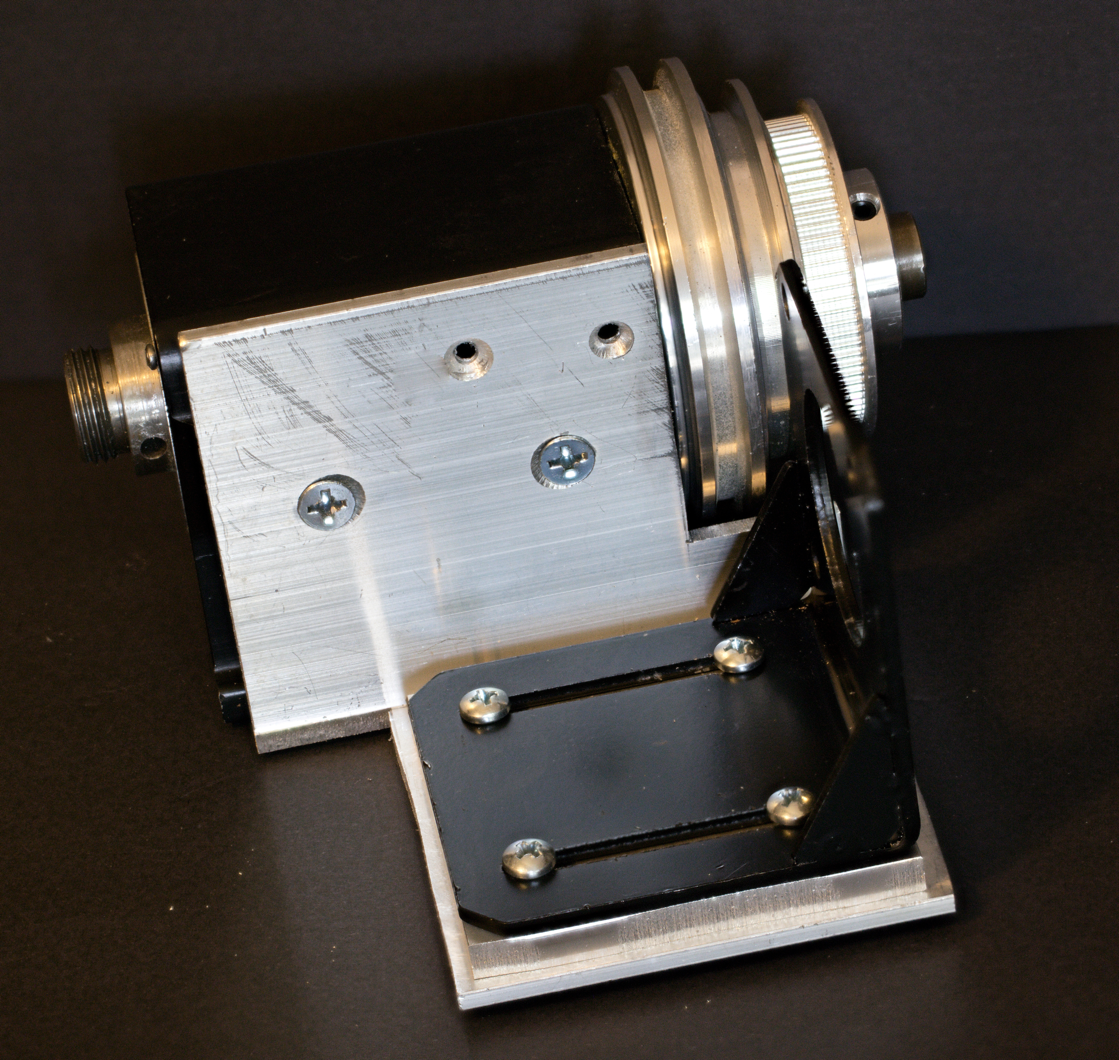
Figure 3: stepper
motor bracket with steel motor bracket
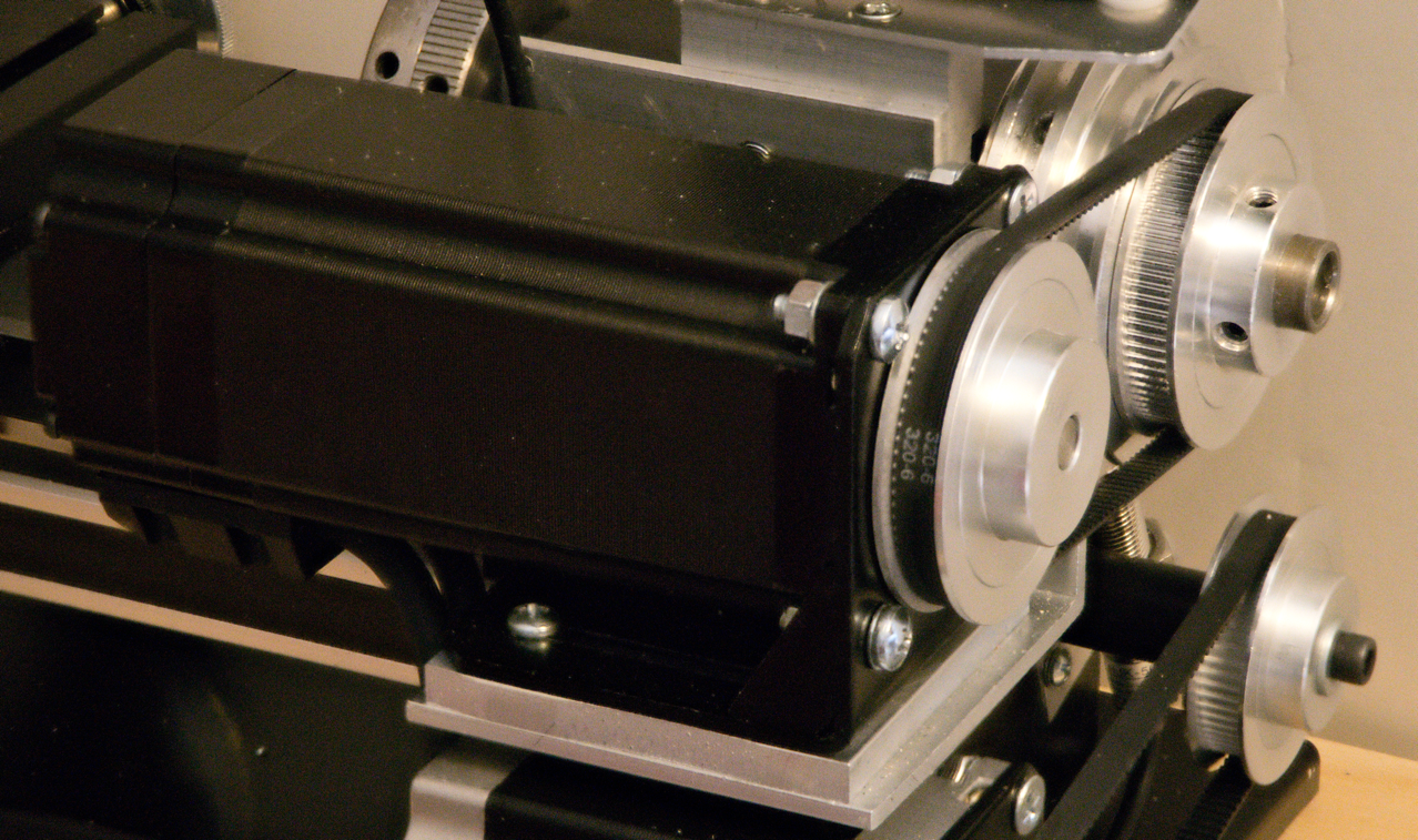
Figure
4 shows the full assembly with the stepper motor, the timing pulleys on the
stepper motor and the spindle as well as the timing belt and with the assembly mounted
on the lathe. Note the flathead screw in
the upper right corner of the stepper motor to provide clearance for the timing
belt.
 X
X
Figure 4: stepper
motor installed on lathe
I
cut a hole in the plywood base so I could run the stepper motor cables under
the plywood so they would not trap chips from the lathe. I also screwed a small piece of 2mm thick
styrene that had one edge shaped to the profile of the cables going through the
hole so that it covered the hole to keep chips out of it. See figure 5.
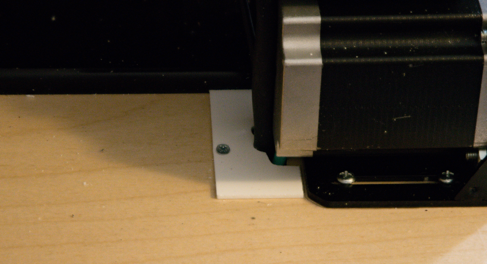
Figure 5: chip
shield
I
mounted the box for the electronics on the back right of the base. I ran the stepper motor cables into the
electronics box from under the bottom and connected them to the driver.
Figure
6 shows a diagram of the electronics for the stepper motor drive.
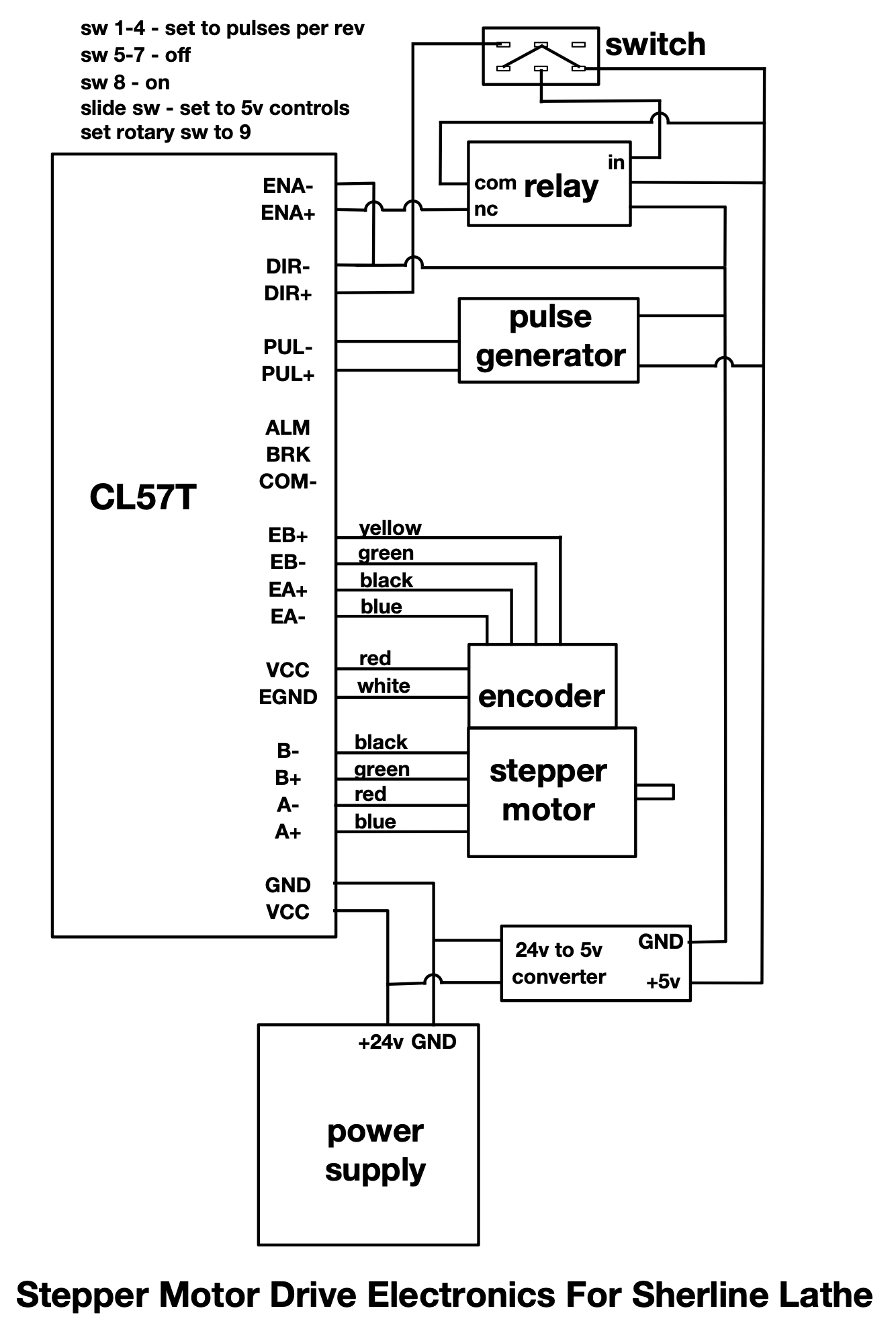
Figure 6: electronics
diagram for closed-loop stepper motor
Finally,
I mounted the switch and pulse generator module on the bracket under the lathe
bed and connected them to the electronics box. See figure 2 in Sherline Lathe
Infrastructure.
Stepper
motor speed
The
pulse generator is used to control the speed of the spindle motor. The speed can be set to anything between
barely moving to more than 2,000 RPM. Note that you cannot start the motor if
the speed is above about 500 RPM since it will stall. Instead, if you need a high spindle speed,
you start it at a slower speed and increase the speed while its running. You should also slow the motor down before turning
it off to minimize the stopping jerk and to set the pulse generator to a speed
lower than 500 RPM for the next time you start the motor. Note that you should not switch directly
between forward and reverse directions, you should stop the spindle before
switching to the other direction. If switch 8 on the CL57T is set to on the
motor starts more reliability but there is a few second pause between when you
turn on the switch and when the motor actually stars.
Stepper
motor speed vs torque
One
thing to keep in mind about stepper motors.
Stepper motor output torque inversely proportional to the speed. I.e, the
peak torque is at low speed and the faster you go the less torque the motor
puts out. So, if you want cutting power
on a lathe with a stepper motor drive, you want low RPM.
Little
Machine Shop provides a calculator as to
what spindle speed
should be used when turning particular materials on a lathe. It is quite useful but you need keep in mind
the torque curve of the stepper motor when deciding what spindle speed to
actually use and what depth of cut to make.
Parts
list for stepper motor drive
I’ve
included links for the parts at Amazon.
The same parts are available from other suppliers if you would rather
not deal with Amazon.
CL57T Closed-loop
Stepper Driver and Stepper Motor Kit
Mounting bracket
for the stepper motor
timing pulleys (2)
– 80 tooth, 8mm bore, for 6mm belt
Copyright
Ó 2024 Scott
Bradner
2024-09-05