Hacks
on a Sherline Lathe
I
have been a happy user of an 8-inch Sherline lathe
for many years. I used the lathe mostly
as it was when it arrived from Sherline. The only
thing I added to the lathe itself was a digital read out system (DRO).
When
I got the new lathe, I decided to add a number of features including a 2 axis DRO,
X-axis power feed, tachometer, and a stepper motor drive for the spindle.
These
additions involved adding two stepper motors with associated pulleys and belts,
a control panel with two switches and 3 display modules, a box full of
electronics, DRO sensors and displays, a power supply, a hall effect sensor,
and a hollow base. See the following separate articles on each of the additions.
Here
is a description, and some photos, of the result of the hacks that depend on
electricity.
Lathe
from the end
Figure
1 shows the lathe from the end. At the
bottom you can see the lathe base made up of a ½” sheet of furniture grade plywood
with strips of ¾” plywood glued to it along the edges so that there is a ¾ inch
high hollow under the ½ inch plywood. The
bed is 27 ½ inches wide by 10 inches deep and is protected with a few layers of
polyurethane.
The
two stepper motors are to the left. The
lower one is for the power feed and is tied to the lead screw with the lower
pair of pulleys and a belt. Hiding under the lead screw pulley is the hall
effect sensor for the tachometer. Just to the right is the handle that is used
to engage the power feed. The upper
stepper motor is for the lathe drive and is tied to the headstock spindle with
the upper pair of pulleys and a belt. To
the left at the back is the side of the electronics box. At the top is the back
of the display for the X axis DRO. At
the left you can see the thin black cord to the power supply for the DRO
display.
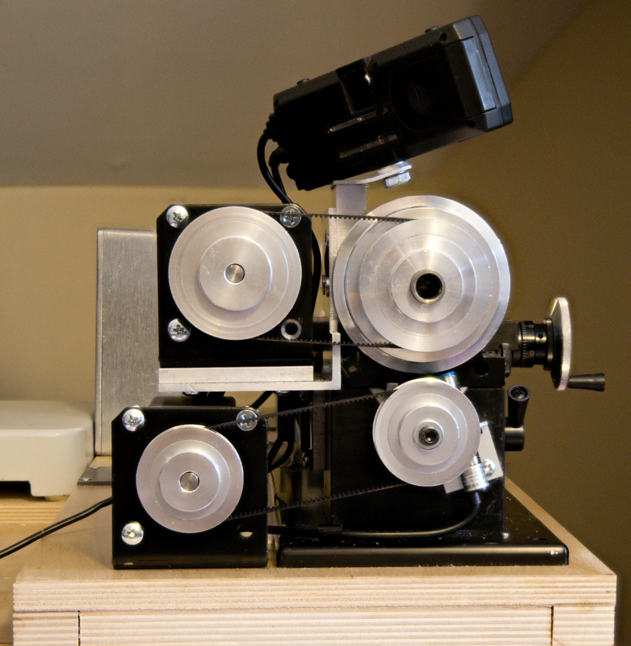
Figure 1: Lathe
from head end
Lathe
from the front
Figure
2 shows the lathe from the front. As with Figure 1, at the bottom is the hollow
base. You can see the three display
modules and the two switches under the lathe bed. Starting from the right, you
can see the spindle motor switch. It is a three position (ON-OFF-ON) switch
with a vertical orientation. The spindle motor is off if the switch is in the
center position. If the switch is up the spindle turns in the direction that the
spindle turns with the Sherline motor and control.
Turning the switch down causes the spindle to turn in the reverse direction.
To
the left of the switch is the pulse generator, which controls the speed of the
stepper motor.
To
the left of the spindle motor pulse generator is the display for the
tachometer. To the left of the
tachometer display is the switch for the power feed. It is a three position ( (ON)-OFF-(ON)
) switch arranged in a horizontal orientation.
Pushing the switch to the right causes the lathe saddle to move right,
pushing the switch to the left causes the saddle to move left. The switch is a momentary one so you have to
hold the switch to keep the saddle moving.
To the left of the power feed switch is the power feed pulse generator
that controls the speed of the saddle movement.
To the left is the pedestal for the headend of the lathe. On the front
of the pedestal, you can see the engagement lever that enables the power
feed. The power feed is disengaged if
the lever is to the left and engaged if the lever is to the right. On the left side of the pedestal, you can see
the hall effect sensor for the tachometer.
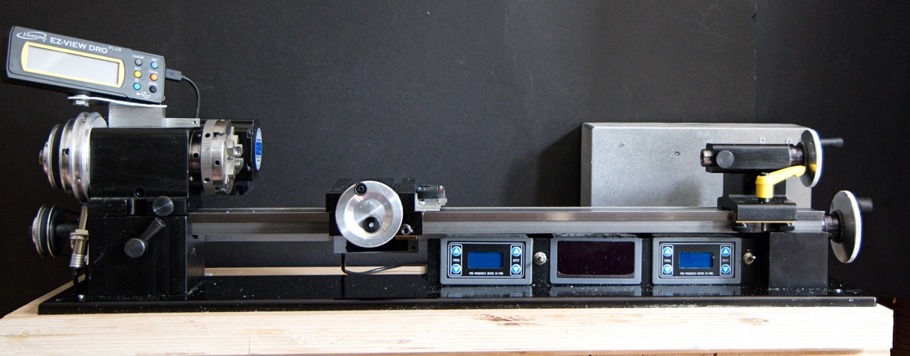
Figure 2: lathe
from front
Control
panel holding bracket
Figure
3 shows a section of the bracket I used to hold the switches and control
panels. The bracket is made from a 1 ½ x
1 ½ x 1/16 aluminum angle. The 1 ½
height just clears the saddle nut that connects the saddle to the lead
screw. Note that you need to cut the top
lip from the bezel on the pulse generator and tachometer display modules to
keep them under 1 ½ inches high. (See
figure 4.) Note that if you have
installed the Sherline Lathe Leadscrew Backlash
Lock Upgrade
you have to position the bracket further back on the base to clear the adjustment lever.
The
cutouts in the front of the bracket are just wide enough for the modules to be
inserted while allowing the wings on the module to grip the opening. The width of the opening for the pulse
generators is not the same as the width of the opening for the tachometer
display. Note that you need to make a
notch in the bottom of the bracket to clear the wires connecting the pulse
generator modules to the electronics box. I painted the bracket black so that it would
blend into the lathe color scheme. (See figure 2.)
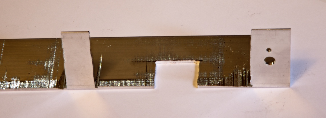
Figure 3
The
holes in the vertical part of the bracket to the right of figure 3 are for a
switch. The lower and bigger hole is for
the switch stem and the smaller hole above it is for the anti-rotation
washer. To the left of the switch holes,
you can see the opening for a pulse generator and, to the left of that, part of
the opening for the tachometer display.
You can also see the cutout on the base of the bracket for the wires to
and from the pulse generator. The same
kind of cutout is not needed for the tachometer display because of the way the
wired run.
I
drilled #33 holes in the bracket and corresponding #43 holes in the lathe base. I tapped the holes in the base for 4-40
screws. I used 3/8 4-40 pan head screws to hold the bracket to the lathe base.
Cables
from the controls and switches to the electronics box.
A
cable is needed between each of the switches and between each of the pulse
generators and the electronics box. In
addition, the flat cable for the tachometer display must be routed to a hole
next to the base in order to connect to the cable from the hall effect sensor
under the base. If left as-is, the cables would create a major shaving and chip
trap and make the lathe very hard to clean.
See figure 4 which shows the connecting cables. Figure 4 also shows some wood blocks I added
to support a plastic shield to cover up the wires.
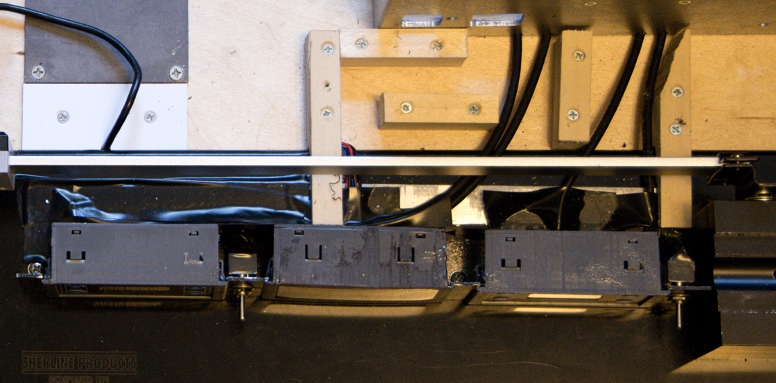
Figure 4: lathe
top view showing cables to controls
Figure
5 shows the same view as figure 4 after the plastic shield has been installed.
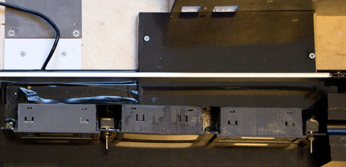
Figure 5: lathe
top view showing chip shield over cables
I
used wide electrical tape to cover the cables from the power feed pulse
generator and power feed switch to where they would be covered by the plastic
shield. I used some 5
minute epoxy to fix the pulse generator modules and the tachometer
display module to the bracket after they were installed so that they would not
loosen and interfere with the saddle nut.
Note that the cables between the stepper motors and the electronics box,
the cable for the DRO and the cable for the tachometer all run in the hollow
under the lathe base in order to keep the area behind the lathe clear and easier
to clean. See figure 7.
Lathe
from back
Figure
6 shows the lathe from the back. At the left you can see the box for the
electronics. In the center you can see
the sensor for the X axis DRO and its cable, which goes under the base. On the
right you can see the two stepper motors, one above the other. The lower stepper motor is for the power feed
and the upper one drives the spindle.
You can also see the ventilation holes I cut into the electronics
box. The ventilation holes are protected
by fine stainless steel mesh that I secured to the
inside of the box with 5 minute epoxy.
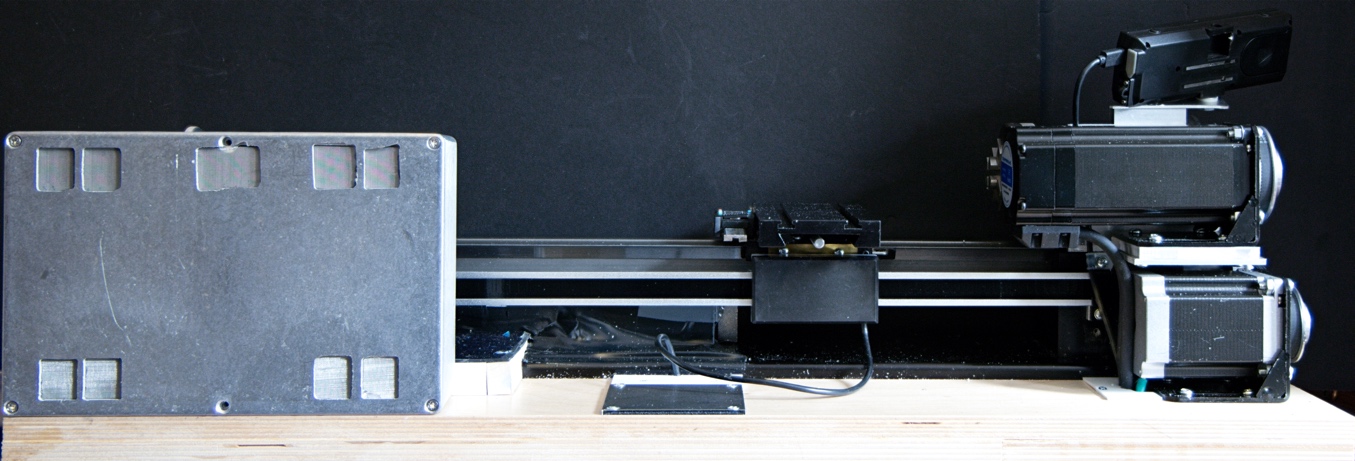
Figure 6: lathe
from back
Lathe
from bottom
Figure
7 shows the lathe from the bottom. The figure shows the hollow base and shows
the wires in the base. I ran the wires
in the hollow base to keep the area around the lathe as clear as possible of
anything that could trap shavings and chips generated but the lathe during its
operation. It also shows the four 25/32 inch high rubber feet.
The feet provide a more stable footing than the plywood edge does but do
not leave a big gap under the base for things to get lost in.
The
lathe is bolted to the base using the four ¼-20 bolts that Sherline
uses to secure the lathe during shipping, they can be seen to the left &
right in the lower third of the picture.
The large holes near the mounting bolts are to provide access to the
captive bolts that are used to secure the lathe bed to the pedestals on the
machined base.
The
terminal junction block in the left of center is for the tachometer
wiring. The green cable at the very top
is the cable for the power feed stepper motor.
The silver connector in the center is for the cable to the spindle drive
stepper motor and the black connector above it is for the cable for the encoder
on that motor. The other wire is for the Y axis DRO.
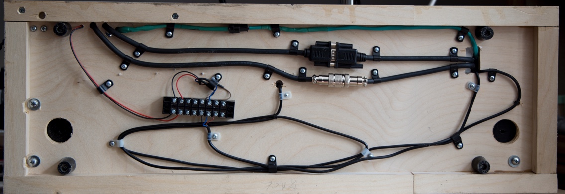
Figure 7: view
under lathe base
Electronics
box.
Figure
8 shows the inside of the electronics box.
At the left you can see the CL57T Closed-loop Stepper Driver that I used
to control the spindle drive stepper motor.
At the right you can see the TB6600 Microstep Driver
that I used to control the power feed stepper motor. In the center you can see the two relay modules
used to invert the enable signals from the control switches. At the lower left you can see the 4-lug
terminal strip I used to terminate the cable from the power supply. Note that I used a nylon screw and nylon washers
to make sure that there was no voltage leakage from the power supply to the
electronics box. You cannot see it, but I used thermal grease between the
stepper motor control modules and the aluminum case to help with heat
dissipation, even though the modules do run quite cool.
As
a test, I ran the lathe with the spindle drive stepper motor running at 500 RPM
for 5 hours after which the temperature of the motor was 10
degrees above the temperature of the crosslide, which
I used as a reference. The temperature of the electronics box was 2 degrees
above the temperature of the crosslide. I then upped the speed to 1,000 RPM and
checked the temperatures after 2 hours of running. The motor was 27
degrees above the temperature of the crosslide and
the electronics box was 4 degrees above the temperature of the crosslide. These are
not temperatures that should cause any worry.
I drilled holes through the plywood lathe
base and through the bottom of the electronics box for the cables from the
stepper motors and for the power leads for the tachometer. I also drilled holes along the bottom front edge
of the box for the cables from the control switches and pulse generator
modules.
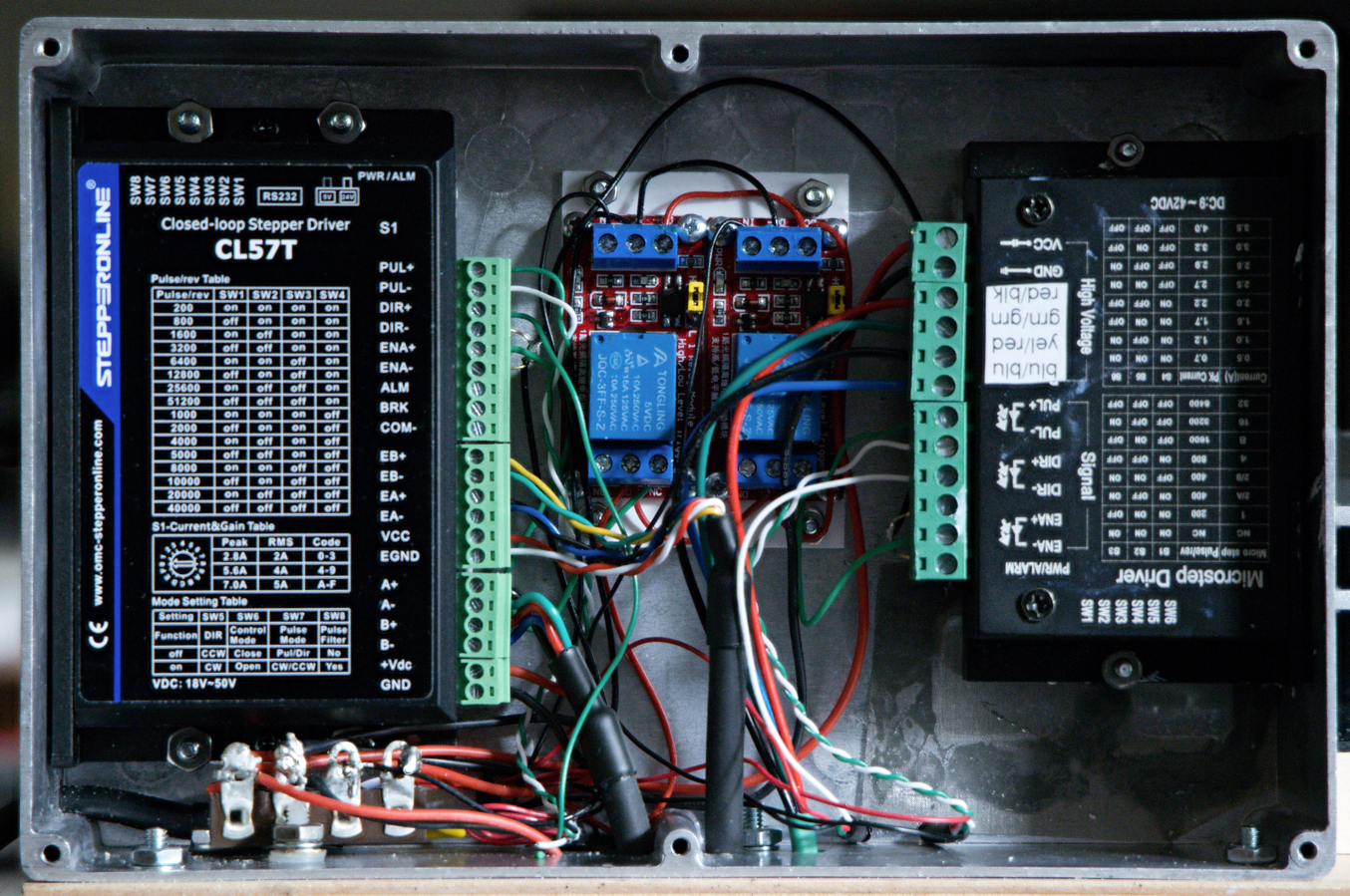
Figure 8: lathe
electronics box
Power
supply
The
stepper motor drivers and the tachometer need 24 vdc while the relay modules
and the control signals for the drivers require 5 vdc. I got a 24 vdc power supply and a 24 vdc to 5
vdc converter module. I attached the
converter to the side of the supply with 2-sided foam tape and wired the
converter inputs to the power supply.
Then I wired both the power supply and converter outputs to a 4-pin
connector. I wired a matching connector to a cable that I then ran to the
electronics box. I plugged the power
supply into a switched circuit so I could turn the lathe on and off. Finally, I
attached the power supply to the side of the tool chest that servers as a base
for the lathe with a pair of angle brackets and some cable ties. See figure 9.
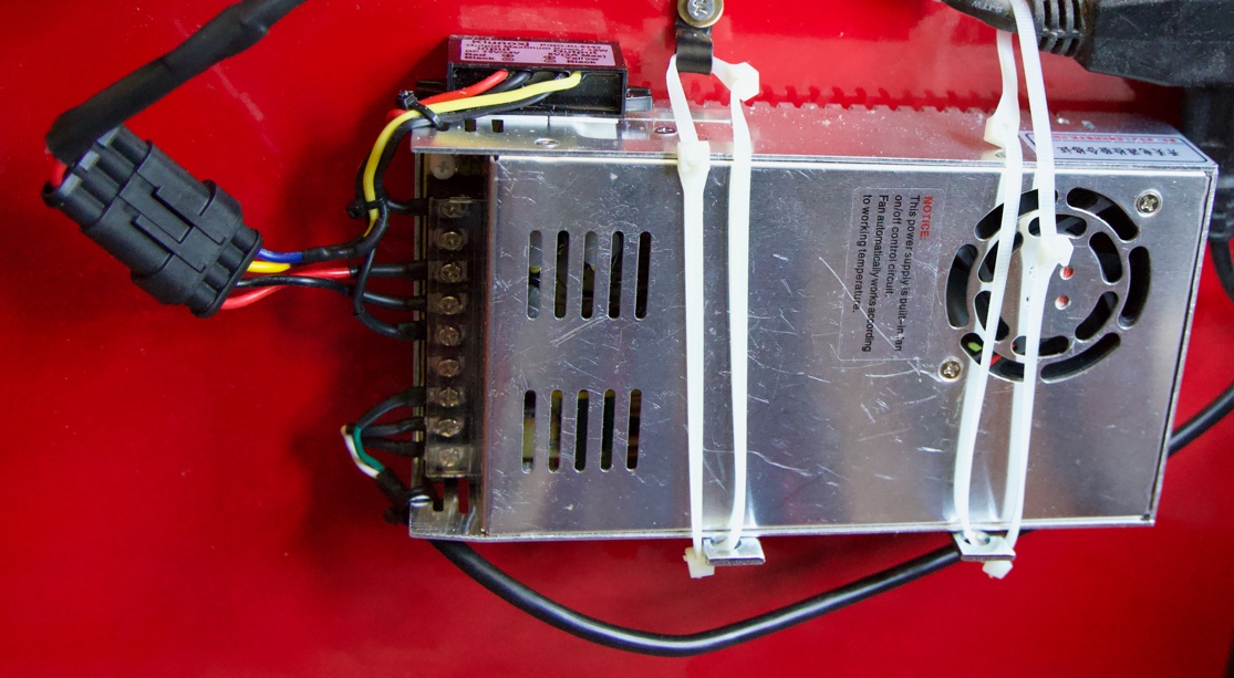
Figure 9: power
supply attached to tool chest
Parts
list
The
parts for the individual additions are listed in the articles describing
them. The parts list here covers the
common elements described in this article.
I’ve included links for the parts at Amazon. The same parts are available from other
suppliers if you would rather not use Amazon.
24 vdc to 5 vdc converter 3 amp
Control module holding bracket - 1.5
x 1.5 x .062 aluminum angle
Electronics box -
8.75" L x 5.74" W x 2.25" H
Stainless Steel Mesh – 120 mesh
Terminal junction block - 6 pole
Power supply cable – 4 strand 18 GA
Cable
to switches & control modules – 4 strand 26 AWG
Amazon sold out – substitute
6 strand
Copyright
Ó 2024 Scott
Bradner
2024-09-05