Bilge Pump Flywheels
I needed to make a pair of flywheels for the bilge pumps on the 1:96 model of the Flying Cloud. Figure 1 is the drawing I made using the pump in the Heinrich Paasch 1890 encyclopedia[i] as a guide. (See Figure 2.) This is the same guide that F Alexander Magoun used when drawing the bilge pump for his 1926 plans of the Flying Cloud. I also used a photo I had taken of the bilge pump flywheel on the Cutty Sark. (See figure 3.)
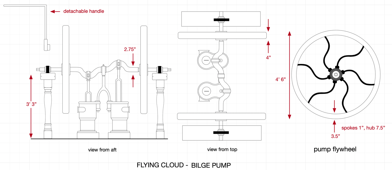
Figure 1
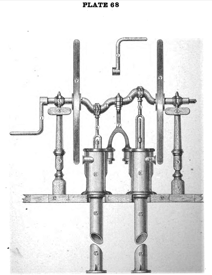
Figure 2 - Paasch. Plate 68
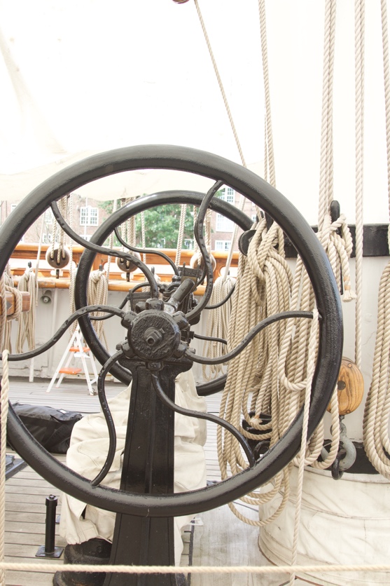
Figure 3 – Cutty Sark pump flywheel
I had already made the main mast pad with the stanchions and rails. I had also made a model of the pump units themselves out of boxwood and brass tubing, and had painted them green. See figure 4.
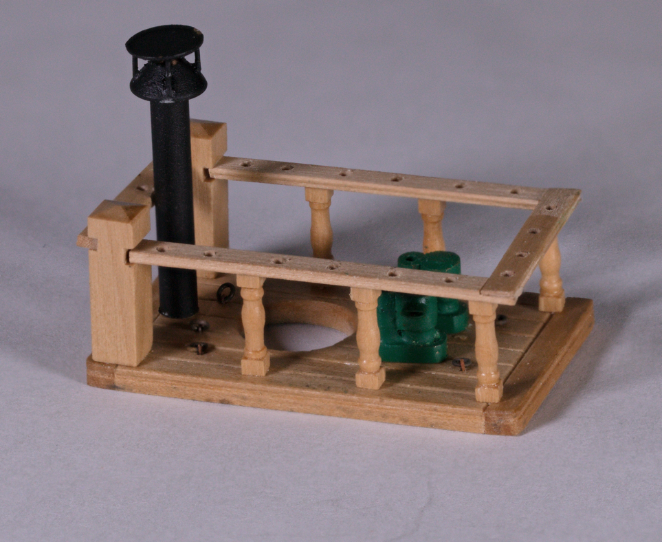
Figure 4 – Main Mast pad with pump units.
I turned the wheels from a brass bar using my Sherline lathe. I turned 3 separate wheels on the same base and left then as one unit for finishing and drilling. I also turned the hub out of a smaller brass bar and also left 3 hubs on the bar for the same reason. Figure 5 shows the turnings for the wheels and hubs after I cut off two of each for the model.
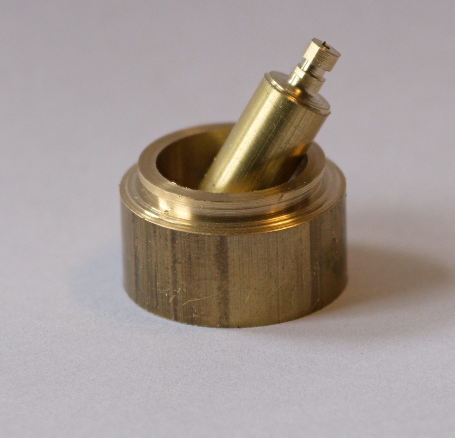
Figure 5 – turnings for the pump wheels and hubs
I then used my Sherline mill and rotary table adapter[ii] to drill six holes in the wheels and hubs for the spokes. See figures 6 and 7.
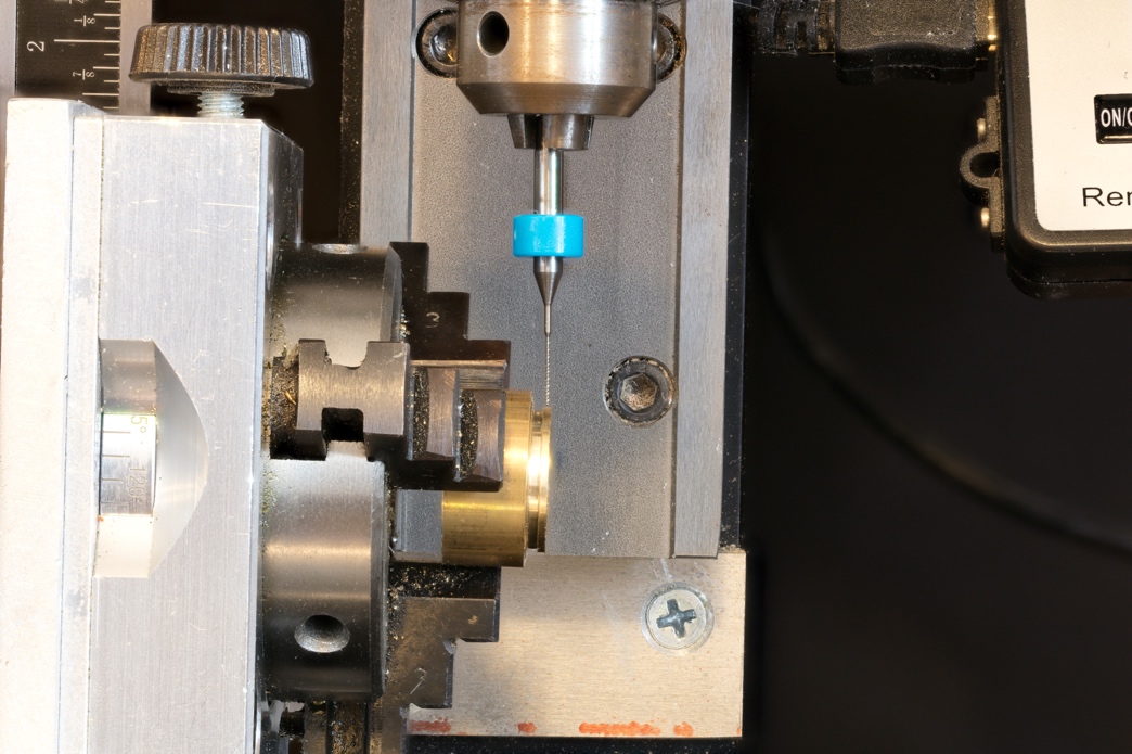
Figure 6 – drilling a wheel
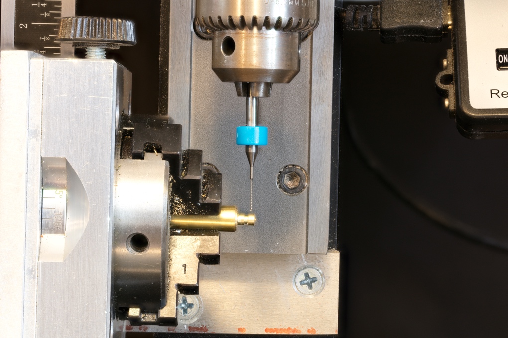
Figure 7 – drilling a hub
Figure 8 shows the wheel and hub after cutting them off of the brass rods and after drilling.
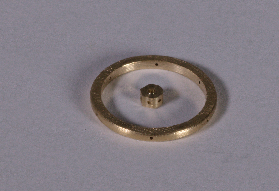
Figure 8 – wheel and hub after drilling
I then needed to make the spokes. I used a setup that Rob Napier had shown me. Two properly sized brass rods in a wooden block with an actual sized plan glued to the block. I then bent some 0.012 brass rod around the pins following the pattern in the drawing. See Figure 9 for the jig.
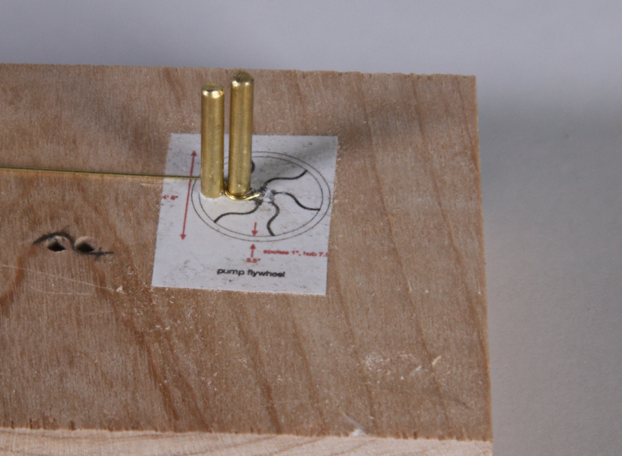
Figure 9 – spoke bending gig.
Figure 10 shows a number of spokes after bending.
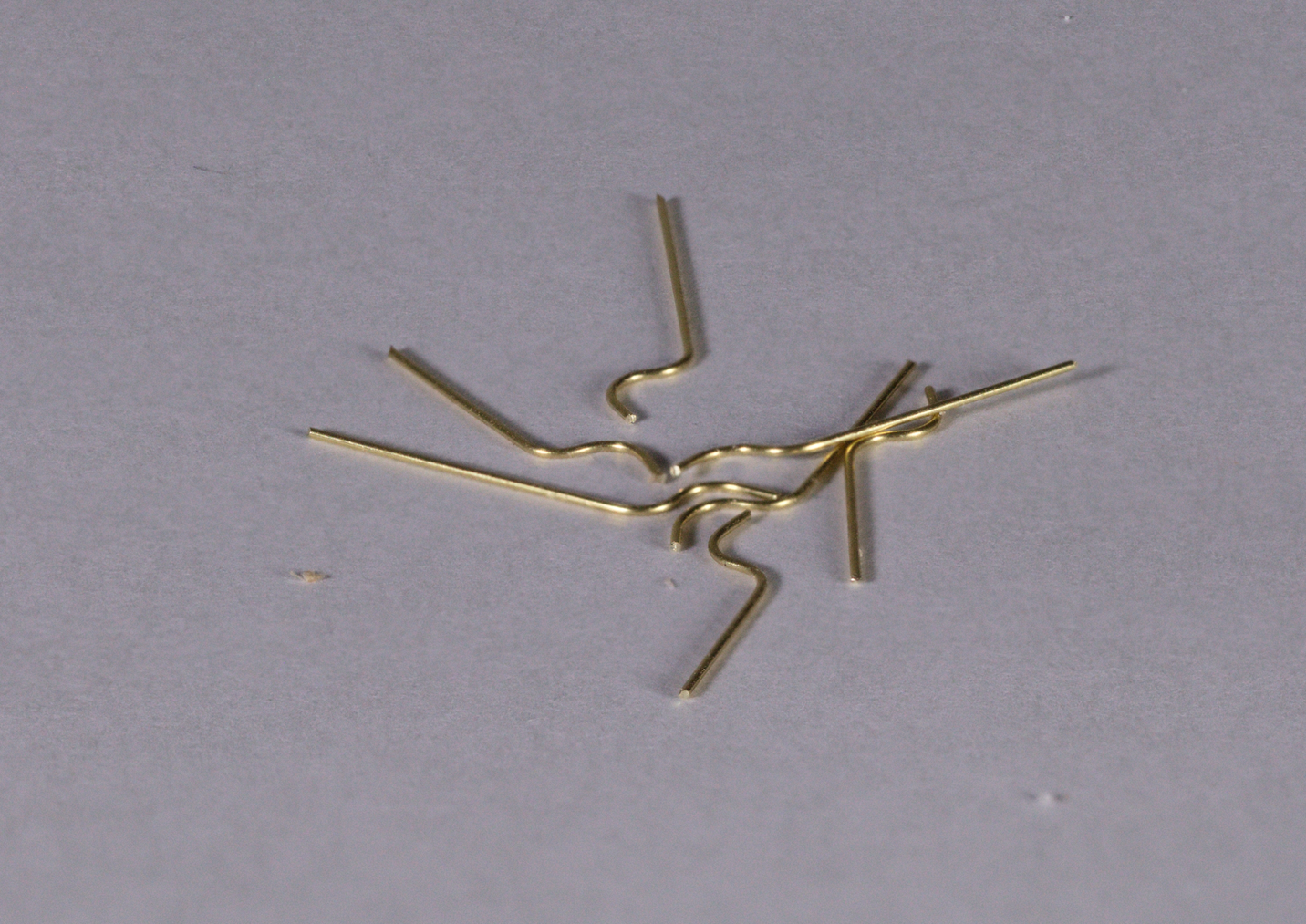
Figure 10 - spokes
I then assembled the wheels, hubs and spokes on a soldering pad. I used a scaled drawing as a guide, something that Rob had also shown me. See figure 11.
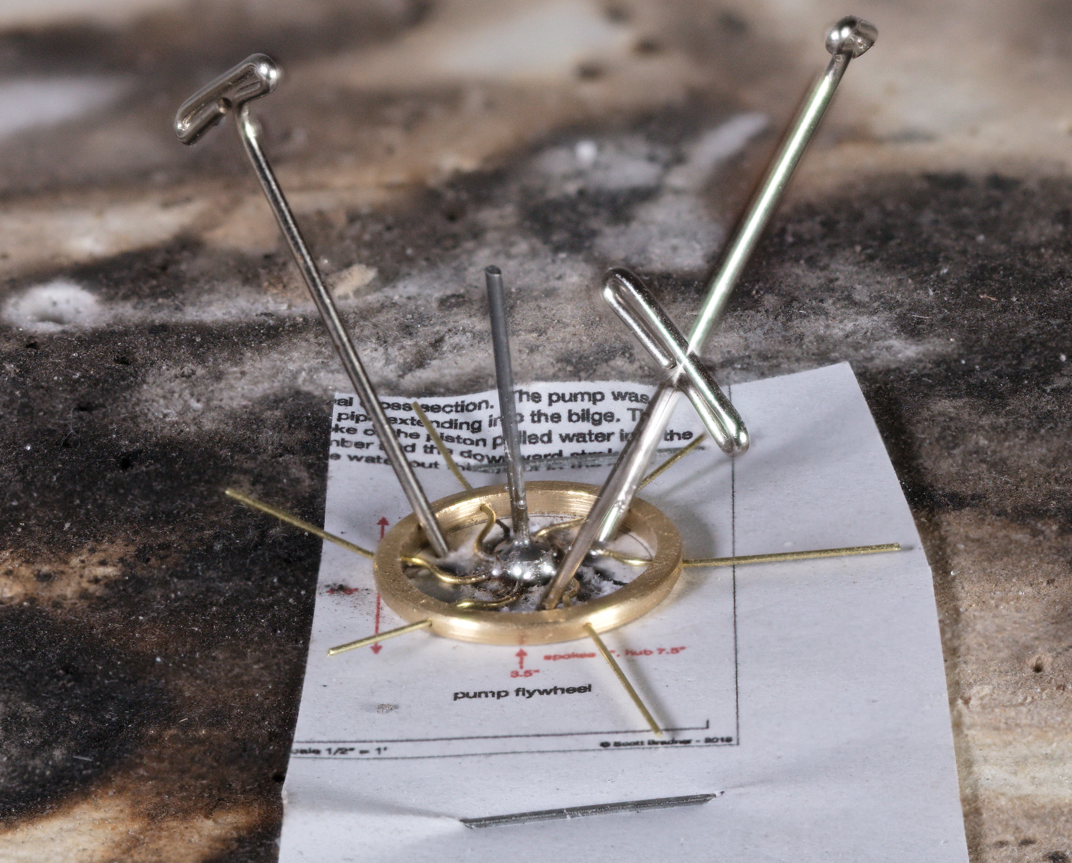
Figure 11. Soldering jig
For the soldering I used low temperature paste solder and a soldering iron. See figure 12. I found it hard to keep the amount of solder paste low enough so there was a lot of post-soldering cleanup. I only soldered the spokes at the hub since the wires held the flywheel in place without solder.
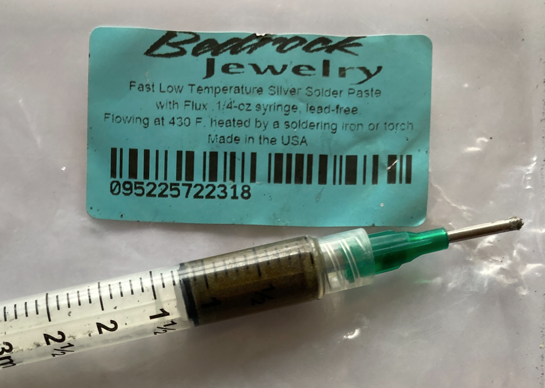
Figure 12 – low temperature paste solder.
Figure 13 shows the soldered flywheel with the spokes trimmed.
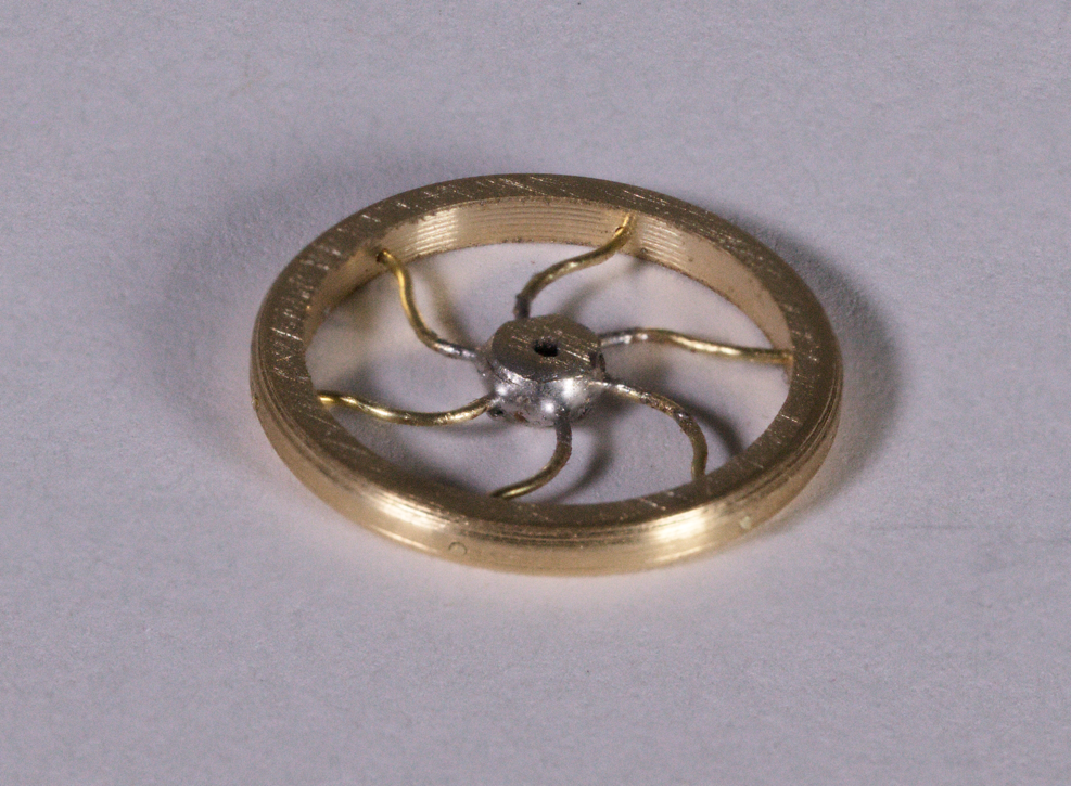
Figure 13 - soldered wheel
I then painted the flywheels red and the spokes and hub black. See Figure 14.
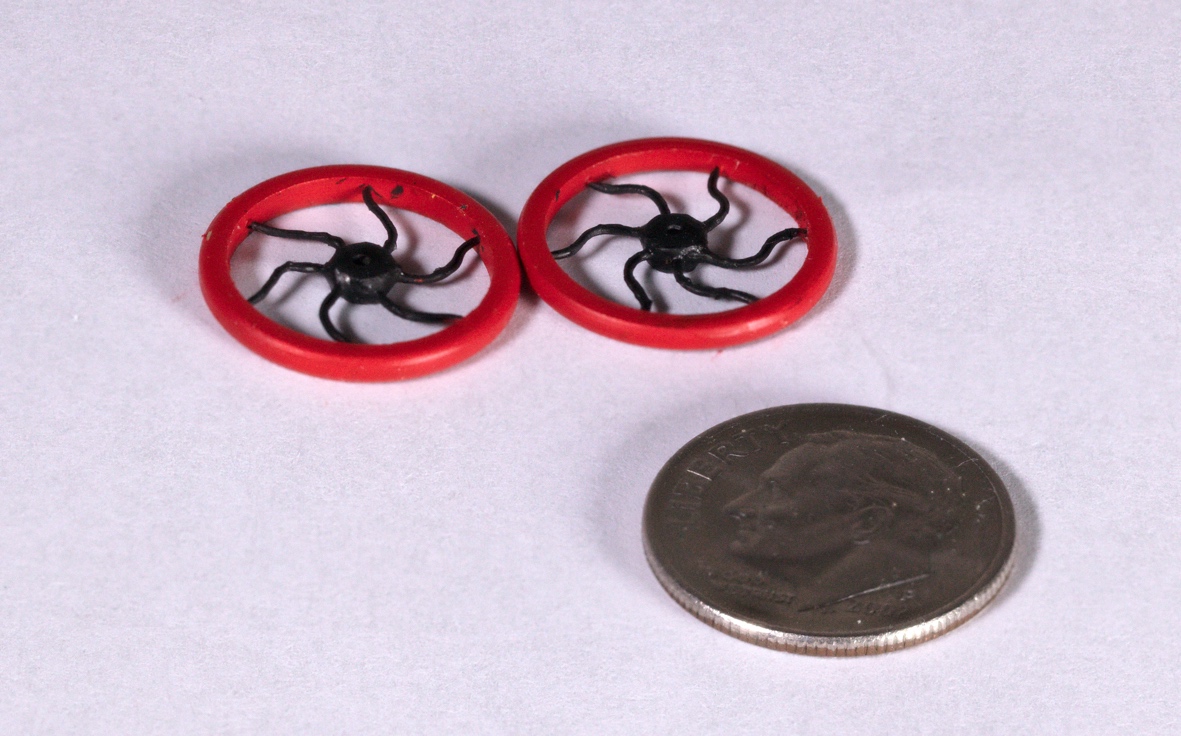
Figure 14 painted wheels with a dime for reference
I then mounded the flywheels onto a crank made of a bent wire and cranks made of bent 1/32 x 1/64 brass bar. See figure 15.
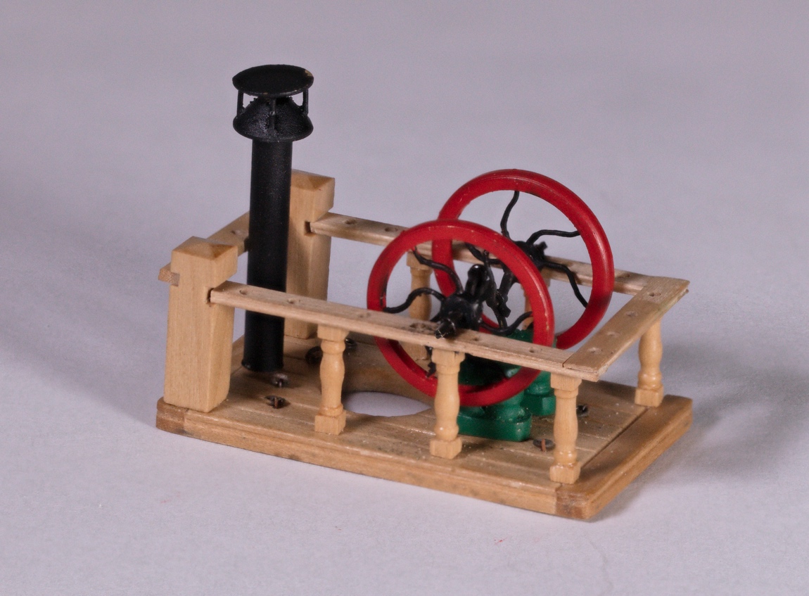
Figure 15 – assembled main mast pad
Figure 16 shows the mast pad with the pumps installed in the model.
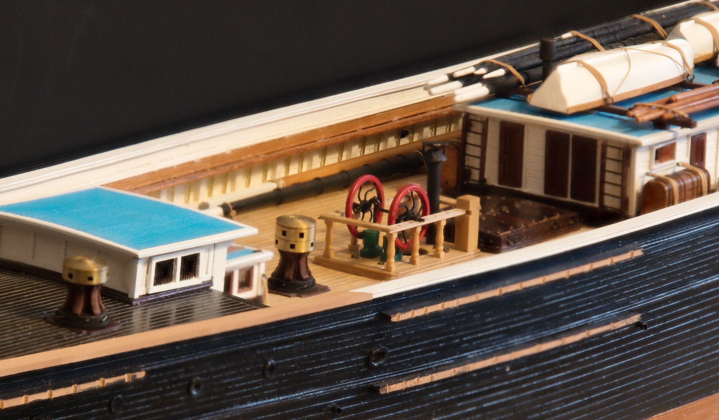
Figure 16 – mast pad installed in model